In the previous designs, we looked at single-hub DMVPN topologies. A single hub is simple, but it also creates a clear single point of failure.
The next logical step is to add a second hub while keeping a single DMVPN cloud.
The goal is to provide hub redundancy while keeping the overlay simple.
Design Goal
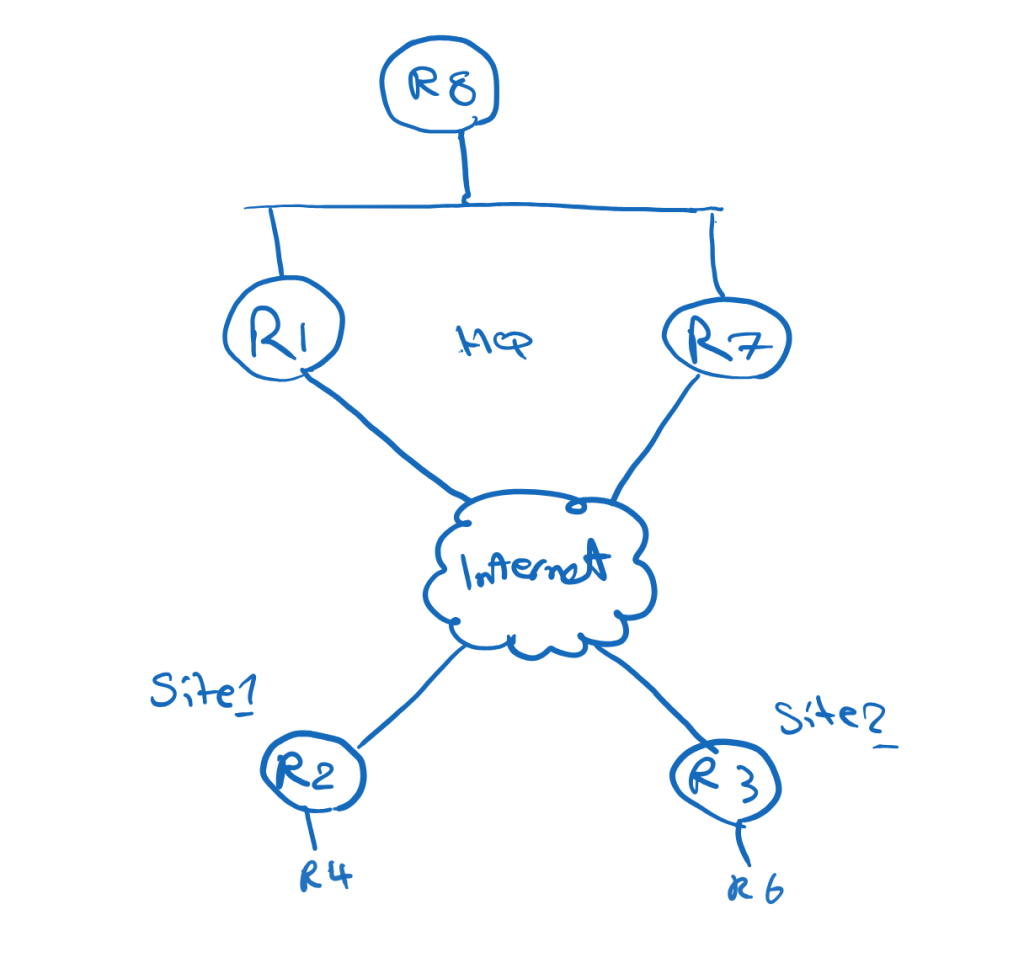
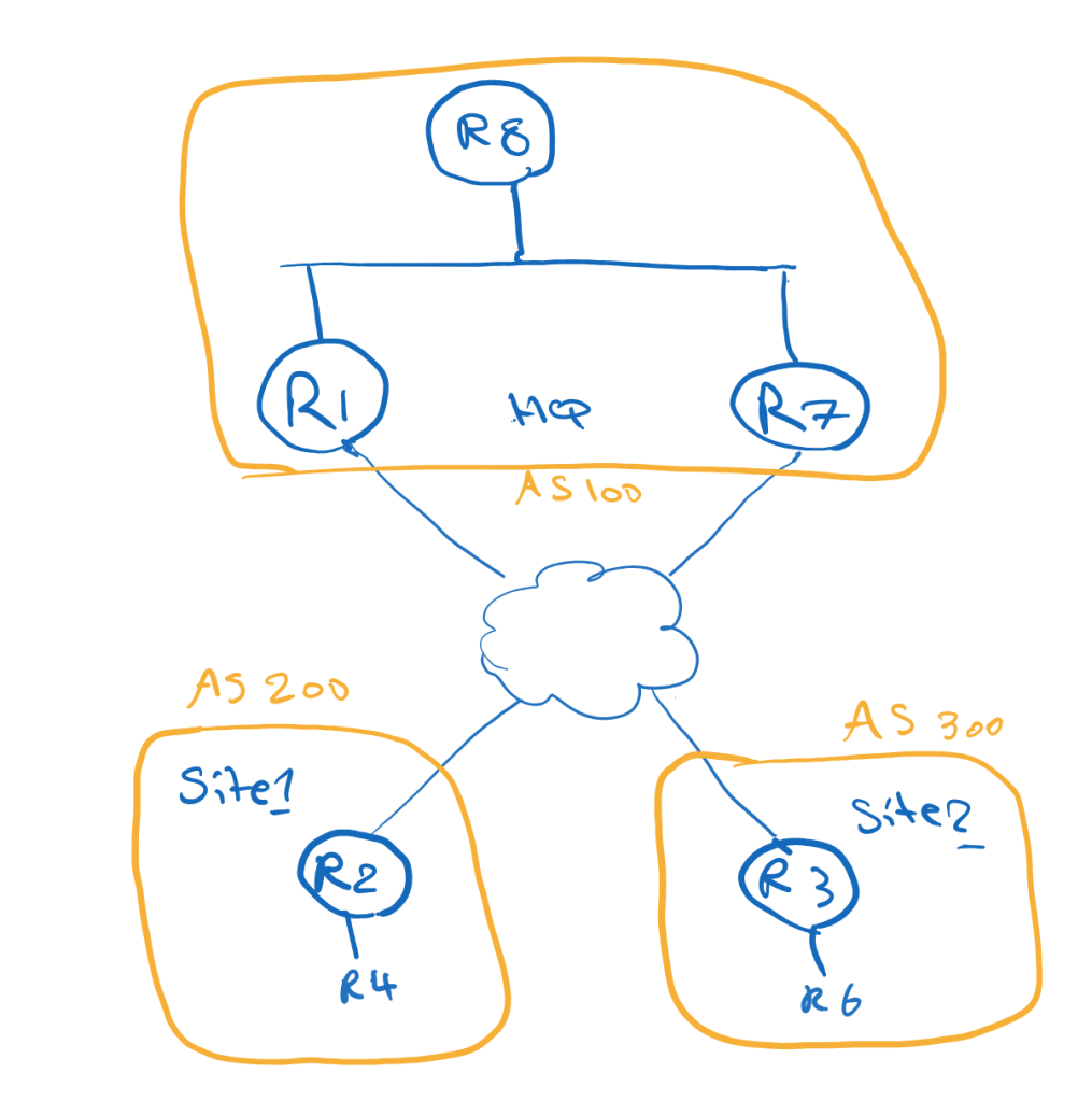
In this topology, The Corporation has two hub routers at the main site:
R1 = Primary HubR7 = Backup Hub
The remote sites use R2 and R3 as spokes.
All routers participate in one shared DMVPN cloud:
Tunnel100 = 100.1.1.0/24
Each spoke registers to both hubs:
R2 → R1 and R7R3 → R1 and R7
The design goals are:
Use R1 as the primary hubUse R7 as the backup hubKeep the spoke routing table smallAllow direct spoke-to-spoke communication
Why Dual Hub Single Cloud?
A dual-hub design removes the hub as a single point of failure.
If R1 fails, the spokes can still use R7 as their NHS and routing next-hop.
Because both hubs and spokes are in the same DMVPN cloud, the overlay remains simpler than a dual-cloud design.
This is an important architectural difference:
Dual Hub Single Cloud = hub redundancyDual Cloud = transport separation
In this post, the focus is hub redundancy.
Main Site Routing Challenge
The main site has another router behind the hubs, R8.
R8 represents the internal main-site network.
A common issue in dual-hub designs is asymmetric routing.
For example:
Remote site → R1 → R8R8 → R7 → Remote site
This may create operational issues, especially if the path includes firewalls, QoS policies, monitoring tools, or stateful inspection.
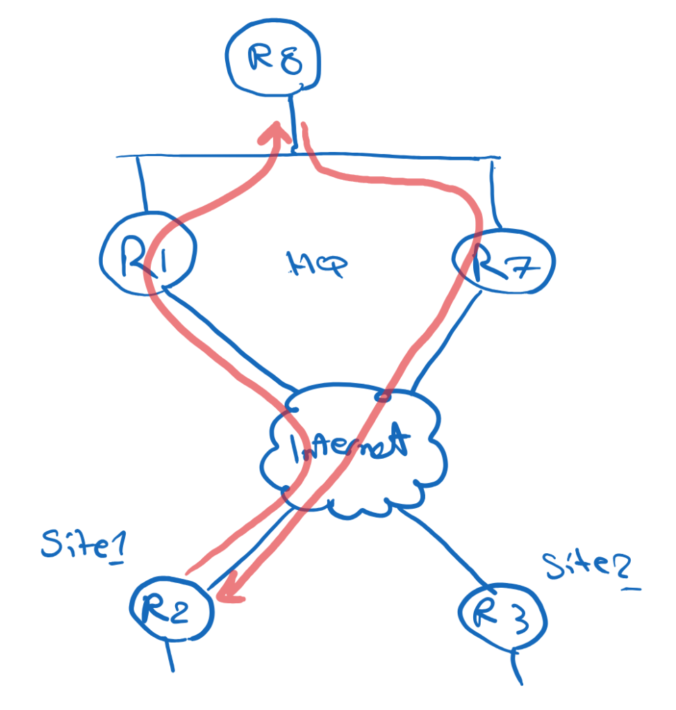
The goal is to keep the return path symmetric.
In normal operation:
Remote site → R1 → R8R8 → R1 → Remote site
During failure:
Remote site → R7 → R8
Avoiding Asymmetric Routing at the Main Site
One clean way to control this is to use specific routes and default routes differently.
R1 advertises specific remote-site prefixes toward R8:
24.1.1.0/2436.1.1.0/24
R7 advertises only a default route toward R8:
0.0.0.0/0
Because specific routes are preferred over a default route, R8 sends traffic to remote sites through R1 during normal operation.
Example on R8:
D 24.1.1.0/24 via 187.1.1.1D 36.1.1.0/24 via 187.1.1.1D* 0.0.0.0/0 via 187.1.1.7
This means:
Specific remote-site routes → R1Default route → R7
If R1 fails, the specific routes disappear, and R8 can use the default route through R7.
This creates a simple primary/backup behavior.
Why Phase 3?
This design uses DMVPN Phase 3.
Phase 3 is useful because the spokes do not need to keep full routing information for all remote sites.
The hub can advertise a summary or default route, and NHRP can optimize forwarding when spoke-to-spoke communication is needed.
The Phase 3 logic is:
First packet: Spoke → Hub → SpokeAfter NHRP redirect: Spoke → Spoke
On the hubs:
ip nhrp redirect
On the spokes:
ip nhrp shortcut
R1 and R7 both act as hubs/NHS routers.
The spokes define both hubs as NHS:
ip nhrp nhs 100.1.1.1 nbma 15.1.1.1 multicastip nhrp nhs 100.1.1.7 nbma 57.1.1.7 multicast
This means each spoke can register with both hubs.
EIGRP Overlay Design
With EIGRP, both hubs advertise a default route to the spokes.
On R1 and R7:
interface Tunnel100 ip summary-address eigrp 100 0.0.0.0 0.0.0.0
Initially, the spokes may receive equal default routes from both hubs:
D* 0.0.0.0/0 via 100.1.1.1D* 0.0.0.0/0 via 100.1.1.7
This may create ECMP, which is not the design goal.
To make R1 the primary hub, we can make the routes advertised by R7 less preferred.
For example, on R7:
router eigrp 100 offset-list 0 out 500 Tunnel100
After this, the spokes prefer R1:
D* 0.0.0.0/0 via 100.1.1.1
R7 remains available as backup.
EIGRP Failover Behavior
In normal operation, traffic from a remote site to the main site follows R1:
R4 → R2 → R1 → R8
For spoke-to-spoke traffic, the first packet may go through R1:
R4 → R2 → R1 → R3 → R6
Then NHRP redirect and shortcut allow direct forwarding:
R4 → R2 → R3 → R6
If R1 fails, the spokes remove the default route through R1 and install the default route through R7:
D* 0.0.0.0/0 via 100.1.1.7
Now traffic to the main site uses R7:
R4 → R2 → R7 → R8
Spoke-to-spoke traffic also starts through R7 and then becomes direct after NHRP shortcut:
First packet: R4 → R2 → R7 → R3 → R6Next packets: R4 → R2 → R3 → R6
iBGP Overlay Design
With iBGP, both hubs can act as Route Reflectors.
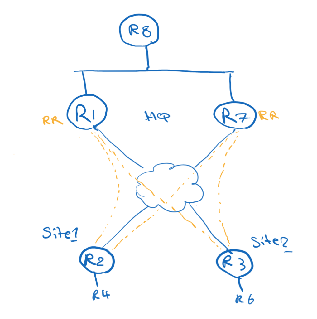
The spokes peer with both hubs:
R2 → R1 and R7R3 → R1 and R7
On the hubs, dynamic BGP neighbors can be accepted with a peer group:
neighbor spokes peer-groupneighbor spokes remote-as 100bgp listen range 100.1.1.0/24 peer-group spokes
Because the hubs are Route Reflectors:
neighbor spokes route-reflector-client
Both hubs can advertise a default route to the spokes:
neighbor spokes default-originate
To prefer R1, apply a higher Local Preference to routes learned from R1 on the spokes:
route-map LOCAL-PREF-R1 permit 10 set local-preference 150
Applied inbound on the R1 neighbor:
neighbor 100.1.1.1 route-map LOCAL-PREF-R1 in
The result:
0.0.0.0/0 via 100.1.1.1 LocalPref 1500.0.0.0/0 via 100.1.1.7 LocalPref 100
R1 becomes the primary hub.
Redistributing BGP Routes Toward the Main Site
If R8 uses EIGRP internally, R1 may need to redistribute the remote-site routes from BGP into EIGRP.
One important detail:
bgp redistribute-internal
Without this command, iBGP-learned routes are typically not redistributed into an IGP.
Then R1 can redistribute BGP into EIGRP:
router eigrp 100 redistribute bgp 100 metric 1 1 1 1 1
This allows R8 to learn the specific remote-site prefixes from R1.
R7 can still advertise only a default route to R8.
The result is the same symmetric-routing logic:
Specific routes via R1Default route via R7
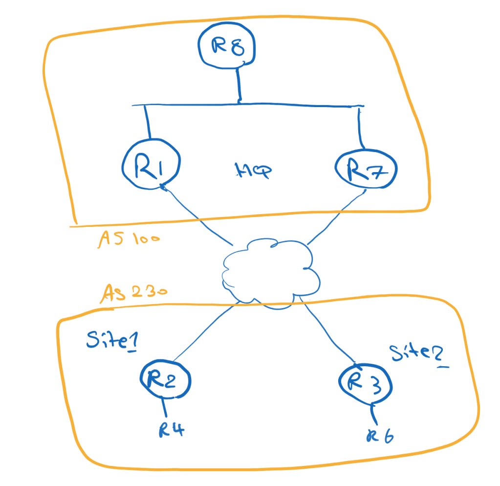
eBGP Overlay Design
eBGP can also be used as the overlay routing protocol.
There are two common models:
Model 1: All spokes in the same ASModel 2: Each spoke in a different AS
Example with all spokes in the same AS:
R1/R7 = AS 100R2/R3 = AS 230
Example with different spoke AS numbers:
R1/R7 = AS 100R2 = AS 200R3 = AS 300
If the spokes use different AS numbers, the hubs can use alternate-as:
neighbor spokes remote-as 200 alternate-as 300
Like iBGP, both hubs advertise only a default route to the spokes.
To prefer R1, Local Preference can again be used on the spokes:
neighbor 100.1.1.1 route-map LOCAL-PREF-R1 in
Because the hubs advertise only a default route, the same-AS spoke design does not necessarily require allowas-in. The spokes are not learning each other’s specific prefixes through BGP; spoke-to-spoke optimization is handled by NHRP.
Why OSPF Is Not Ideal Here
OSPF is not the best fit for this specific Phase 3 design goal.
The reason is summarization and LSDB behavior.
In a single OSPF area, routers need consistent topology information. That makes it difficult to use a clean default-only model from the hubs while still keeping the routing overhead low.
OSPF can work in some DMVPN designs, especially Phase 1 and Phase 2, but for a scalable Phase 3 design with minimal spoke routing information, EIGRP or BGP is usually a better fit.
A good DMVPN design must provide backup paths, but it must also control which path is used during normal operation and how traffic returns from the main site.
This is where routing policy becomes just as important as tunnel configuration.

Leave a comment